


Microsoft Places
How to Create IMDF Files for Microsoft Places


Introduction – What is IMDF?
Developed by Apple, IMDF (Indoor Mapping Data Format) is a standardised format for mapping indoor spaces.
Built on GeoJSON, a widely used JSON-based format for representing geographic data, IMDF provides a structured framework for defining indoor features such as rooms, pathways, and points of interest. This enables seamless integration with various systems, such as indoor navigation, retail and hospitality applications, and building management solutions.
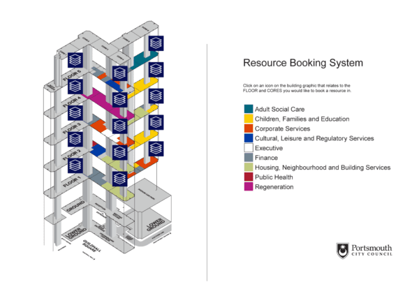
Microsoft Places has adopted IMDF as the standard for displaying indoor maps, enabling users to easily identify available workspaces, and book desks or meeting rooms with an interactive floor plan created using IMDF.
This article explores what IMDF files look like and how to create them and get them ready for upload into Microsoft Places
What Do IMDF Files Look Like ‘Inside’?
An IMDF file is a ZIP file containing multiple individual GeoJSON files that work together to define different aspects of an indoor space.
There are 11 GeoJSON file types specified in the IMDF standard, each of which has a role in describing the different aspects of the venue being mapped.
For example, pathway.geojson is used to map out the walkable routes inside the venue, opening.geojson identifies doors, windows, and other openings and amenity.geojson identifies points of interest (WCs, lifts, etc.).
In the case of Microsoft Places, there are 4 mandatory geojson file types, namely:
- building.geojson – This file specifies the geographic position of the building, anchored by longitude and latitude coordinates.
- footprint.geojson – The describes the overall layout of the building and is represented by a polygon of latitude and longitude coordinates.
- level.geojson– Describes the specific floors or levels within the building structure, and the layout of each.
- unit.geojson – Defines the individual spaces within each level, such as meeting rooms, desks or open areas.
Other ones you can optionally include (and that have been added since the original Microsoft documentation was published) are:
- section.geojson – This file is needed if you want sections to appear on the map. This is where the map starts with a view of the sections across your floor plan, and where clicking on a section automatically zooms into the workspaces in that section. It’s ideal if you have a large office floor area that has distinct areas or zones your workforce will be familiar with or want to be seated in.
- fixture.geojson – If you want desks to appear with automatically drawn desk icons and with the faces (avatars) of who’s booked them, you’ll need to describe your desk objects in this file (instead of the Unit.geojson).
Note that Microsoft Places expects your the geojson files related to different levels/floors to be together inside the same ZIP, so if you are getting started with just one floor out of say, 3, aim to include the geojson that relates to the other floors.
So, for example, level.geojson should include records for each level, and the unit file should include core things like WCs and lifts and stairs, which are typically the same between floors. Only the workspaces commissioned on your ‘active’ floor need to be defined.
Another important thing to note is that Microsoft may well support other file types in the future and continue to add extensions, so be prepared for changing your IMDF files if you want to take advantage of what may come ‘down the track’.
What Does a Meeting Room Look Like in an IMDF File?
Here’s an example of the code that might be initially generated to describe a meeting room in a unit.geojson file:
{
  "feature_type": "unit",
  "type": "Feature",
  "id": "528f23be-5725-4e46-ab8b-6424311574f3",
  "properties": {
    "name": {
      "en": "MR 01"
    },
    "category": "conferenceroom",
    "level_id": "e11320a3-a7d5-4261-b7a1-8b64c69be6ba",
    "building_ids": [
      "47300485-ee29-4dfb-b658-ddd646fb510f"
    ]
  },
  "geometry": {
    "type": "Polygon",
    "coordinates": [
      [
        [
          -2.760855898465106,
          51.48696421522179
        ],
        [
          -2.760855898465106,
          51.48695291631972
        ],
        [
          -2.7608587946101957,
          51.48695291631972
        ],
        [
          -2.7608587946101957,
          51.48699041984375
        ],
        [
          -2.7607570158863775,
          51.48699041984375
        ],
        [
          -2.7607570158863775,
          51.48695291631972
        ],
        [
          -2.7608377532494233,
          51.48695291631972
        ],
        [
          -2.7608382260818303,
          51.486955431276456
        ],
        [
          -2.760839565803712,
          51.486957811283546
        ],
        [
          -2.760841732985313,
          51.486959958197836
        ],
        [
          -2.7608446094215364,
          51.48696174933663
        ],
        [
          -2.7608480375136057,
          51.48696309882561
        ],
        [
          -2.7608518793355343,
          51.486963933055534
        ],
        [
          -2.760855898465106,
          51.48696421522179
        ]
      ]
    ]
  }
}
Each individual ‘feature’ (in this case, a meeting room) is assigned:
- Unique IDs*, comprising:
- An id for the feature being described
- A level_id – this is a unique identifier that links the room to the specific floor it’s on
- A building_id – this is a unique identifier that links the room to the specific building it’s in
- A category – in this case we say that it’s a conferenceroom – the others that are used by Places are workspace (a desk pool) and desk (an individual desk)
- A Name* – this is the room name – in this instance, “MR 01″**
- Geometry – it’s here that we indicate we are going to show the room as a set of co-ordinates, followed by an array of co-ordinates*** that define the room’s shape.
There could well be objects that aren’t bookable spaces in Places, but are included to depict walls, seating areas, lobbies, and so on, that make up your overall office floorplan.
*Note that these IDs get assigned when your GeoJSON is initially created but will effectively be ‘reworked’ when you upload your IMDF into Places to include the relevant Places IDs as well.
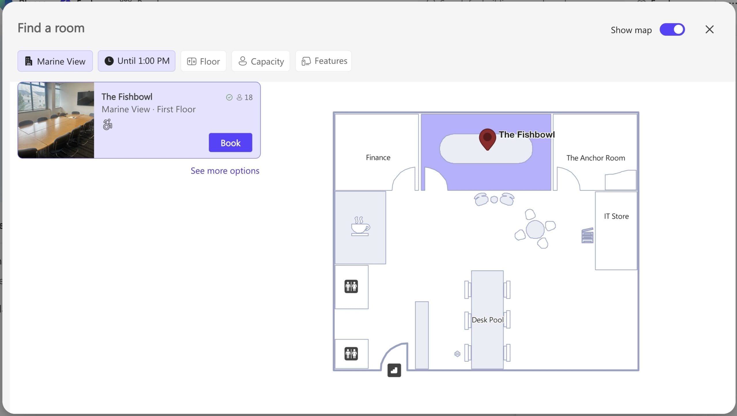
**This may be the actual name of your room or desk as defined in Microsoft Places, but it could be a ‘placeholder’ name that gets mapped later in the process to what it needs to be. Below is what the room described in the above code looks like on the floor plan displayed in Places. If you’re wondering why the indicated desk is named ‘The Fishbowl’ instead of ‘MR 01’, this is covered in this article that explains how to correlate and upload IMDF files into places.
***You will notice that the coordinates of the room geometry are highly precise and are in fact relative to the anchor longitude and latitude coordinates that correspond to the building. Each decimal place increases the accuracy of the location – 6 decimal places will give you around 10 cm accuracy.
How are IMDF Files Created?
As you can imagine, IMDF files can be very large, complex and difficult to troubleshoot – especially if you’re creating them ‘by hand’ (DIY IMDF file creation is possible, and we’ll be writing a blog about how to do this later).
For any requirement that involves multiple floors and multiple office buildings, we recommend you use a dedicated platform or floor plan creation service provider to create your IMDF floor plans.
Companies able to offer this service include Pointr, MappedIn and Mapspeople, each of whom offer a platform for uploading existing maps and turning them into IMDF files.
Mini plug: Essential also offers a white glove floor plan design and IMDF creation service where we take all the work off your hands. This includes the ability to convert floor plans that you may be using in an existing desk booking system.
Want to simplify IMDF creation?
Generally speaking, these are the steps you’d expect to carry out when creating IMDF files using one of these platforms:
1. Upload Your Floor Plans:
Ideally your original floor plans need to be in a vector format such as DWG (e.g., from AutoCAD) or in another vector format such as SVG or PDF. Some platforms also allow you to upload a pixel (raster) graphic format, such as PNG or JPG files, as the starting point.
2. Define the Structure of Your Floor Plans:
The next step is usually to add a hierarchy or structure that links each floor to your building, and the building to its location, with steps that include:
- Assigning each uploaded floor plan to the corresponding office, followed by the level within the office.
- Providing the location or longitude and latitude coordinates of your office location.
- Creating a polygon at ground level to represent your office’s footprint.
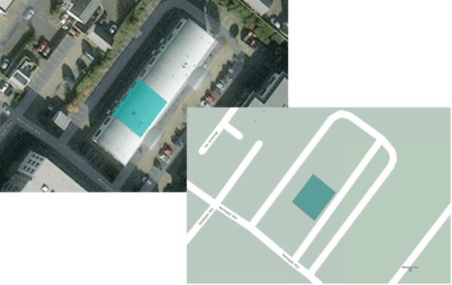
Note that at this point you usually have the option to rotate your office plan so that it reflects its actual north-south orientation. To help with process the map creation service you use will typically display a ‘map’ layer that you can orient to (see examples below).
Note, however, that Places does not itself display a map layer to end users. For this reason (and many others) you may choose a simpler ‘heads-up’ (flat on) layout. See our article on office floorplan orientation.
3. Align your floors & clean up
To create the best user experience, you’ll typically need to do a tidy up. For example:
- Your floors need to be positioned so that they sit directly on top of each other. This way, the floorplans won’t ‘jump around’ as users move from level to level: Consistency is king for getting the best UX!
- You’ll probably need to clean and crop your plans to remove items such as the architect’s information and any wide borders with nothing happening on them!
4. Start adding floor plan features:
In this stage you’ll need to identify and ‘draw’ the key elements that you’d like to see in your floor plan. This of course includes meeting rooms and desks that will be bookable in Places, but also dividing walls, lobbies, etc. that will be crucial to helping users understand where things are.
Depending on your chosen platform and the original format of your floor plan files, a lot of this stage may be done automatically.
For example, if you were able to upload your floorplan in DWG format, there is a lot of ‘intelligence’ baked into this file format that can be automatically ‘pulled out’. Alternatively, most IMDF creation platforms let you ‘trace over’ the various features that you want to show with easy-to-use vector drawing tools.
Our advice here is to take the opportunity to simplify your floor plan. CAD diagrams always provide far more information than is required. Eliminating detail at this stage will streamline both the job of floor plan preparation and ongoing maintenance. It will also help end users of the system quickly find a suitable workspace.
Note that although the platform you use to create your IMDF files may allow you to add points of interest (POI) to your floorplans (such as fire exits and coffee points), there are only a few POIs currently supported in Places. For more information see this article on points of interest.
5. Label your workspaces:
All the relevant bookable workspaces (e.g., meeting rooms, desks) will need to be labelled and this can be done within the IMDF creation platform.
If you initially uploaded DWG files that included meeting room names and desks, these labels may be automatically detected and inserted, but you may need to double-check these.
In our experience, the labels applied in the original architect’s diagrams are just placeholders and bear little relation to the numbering and naming scheme that your FM team wants to use.
Having said all this, there’s an opportunity to re-map the labels used to create your IMDF file to what each entity will be called in Places.
For more information on best practices for numbering your desks check out this article.
6. Export your IMDF file:
You will now be ready to export your finalised IMDF data as a ZIP file.
This is this file that you need to upload into Microsoft Places, and how to do this is described in our related article on how to correlate and upload your IMDF in Places >
Your chosen Places mapping partner may be able to help streamline the process of uploading maps into Places – and indeed – help you cope with the inevitable changes you’ll want to make to add, move or rename workspaces in the future.
A final note again, is that you can also take a DIY approach to creating IMDF files, and we will make this the subject of another blog – but as we indicated earlier it’s hard work!